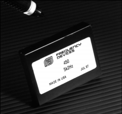
FIXED FREQUENCY OPERATION
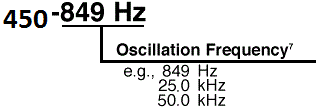
The output signal frequency of each 450 Series sinewave oscillator is factory calibrated to within ±1% of the user-specified value. Independent of frequency setting, the output amplitude is preset to 20V p-p.
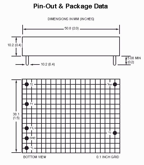
To put the oscillator into operation, simply connect the power supply common, voltages (±Vs), and ground pin T2. Pin T2 must be connected to ground in this mode of operation.
FINE FREQUENCY ADJUSTMENT (±5%)
For applications requiring a more accurate frequency setting, disconnect Pin T2 from ground. Connect a Cermet potentiometer as shown in Fig. 1 for a ±5% frequency adjustment range.

Figure 1.
AMPLITUDE ADJUSTMENT (1 to 20V p-p)
For applications requiring either variable or lower level output signals, a single resistor or a dc control voltage can externally program the D45 output amplitude to any value between 1 and 20V p-p. Warning: Adjusting for outputs below 1Vp-p will cause loss of the output signal.
|
|
Discrete Resistive Programming: The method shown in Fig. 2 (A) provides continuous control of the output amplitude. For both methods, Equation 1 defines the value of R1 for the specific set of conditions.

Figure 2.
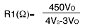
Equation 1.
Vo = Output Voltage in V p-p
Vs = B plus Supply Voltage
Continuous Resistive Programming: To determine the value of potentiometer R1 in Fig. 2 (B), simply insert the appropriate values into Equation 1.
Suppose for example, the required output amplitude range is 1 to 10Vp-p and the positive power supply is +Vs = 15 Vdc. Equation 1 becomes

or potentiometer R1 = 150kohm.
Voltage Programmable Amplitude: The output amplitude of the D45 can be voltage controlled by applying dc programming voltage VT3 to Pin T3. The output response is found from Equation 2, below:

Equation 2
where Vo is the output voltage expressed in Vp-p, and
VT3 is the dc control voltage applied to pin T3.
|