Description
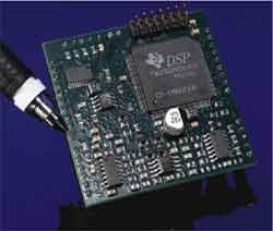
The SPPPF Series of dual channel programmable, FIR filter platforms, are factory configured, turnkey solutions that cover the audio bandwidth to +20 kHz. Each SPPPF-01 provides two independently tuned channels of on-board analog I/O with 9-bit, (512) tuning while each SPPPF-02 provides two independently tuned channels of on-board analog I/O with 8-bit, (256) tuning. SPPPF's are easy to use, plug-in modules with no external components, all packaged in a compact 2" x 2", low profile footprint. Each SPPPF contains its own anti-alias and reconstruction filters along with ADC's, DAC's and analog I/O. The SPPPF's provide brick wall, linear phase characteristics with low noise attenuation floors of -96 dB typical. Sampling at 48 kHz, the fixed point DSP utilizes 32-bit math to achieve 24-bits of precision for digital FIR filters with shape factors from 1.03 to 1.50.
SPPPF's can be provided in several standard or custom frequency ranges utilizing a broad range of single or multi-rate brick wall algorithms. All pre-programmed for your laboratory or field applications.
|
|
Features/Benefits:
- Integrates the best of analog and digital signal processing to optimize standard and multi-rate FIR filter performance.
- Each channel can be programmed independently.
- Provides plug-in turnkey solutions with over 500 digitally programmable algorithms per channel.
- All standard and custom solutions combine Brick-wall Low-Pass, Band-Pass solutions with linear phase performance.
- Compact 2" x 2" dual channel design provides precision performance while minimizing board space requirements.
Applications
- Sound and Vibration Testing
- Signal Correlation / Data Analysis
- Speech Analysis, Research, Pathology
- Research and Development
- Automatic Test Equipment
- Data Acquisition Systems
|
SPPPF-01 Block diagram
SPPPF SOFTWARE SELECTION GUIDE
|
|
|
|
Dual Channel Low Pass Ranges
|
|
SPPPF-01
|
|
SWLP-01
|
|
From 10 Hz to 521 Hz in 1.0 Hz steps
|
|
SWLP-02
|
|
From 10 Hz to 5,210 Hz in 10 Hz steps
|
|
SWLP-03
|
|
From 25 Hz to 12,800 Hz in 25 Hz steps
|
|
SWLP-04
|
|
From 50 Hz to 20,950 Hz in 50 Hz steps
|
|
SWLP-CXX
|
|
Consult factory for custom ranges.
|
|
|
|
Dual Channel Band Pass Ranges
|
|
SWBP-01
|
|
10 Hz BW from 50 Hz to 5,170 Hz in 10 Hz steps
|
|
SWBP-02
|
|
25 Hz BW from 50 Hz to 12,825 Hz in 25 Hz steps
|
|
SWBP-03
|
|
50 Hz BW from 50 Hz to 20,800 Hz in 50 Hz steps
|
|
SWBP-CXX
|
|
Consult factory for custom ranges.
|
|
SPPPF-02
|
| SWLP-05 |
|
From 0.1 Hz to 25.6 Hz in 0.1 Hz steps |
|
|
Analog Input/Output
|
SPPPF-01 Series
Available Dual Channel
Low-Pass Models
|
|
Low Pass
|
Channel Configuration
|
Fc1
|
Step (Hz)
|
Tuning Range
|
|
SWLP-01
|
Two Independent LP FIR filters
|
10
|
1
|
10 Hz to 521 Hz
|
|
SWLP-02
|
Two Independent LP FIR filters
|
10
|
10
|
10 Hz to 5,210 Hz
|
|
SWLP-03
|
Two Independent LP FIR filters
|
25
|
25
|
25 Hz to 12,800 Hz
|
|
SWLP-04
|
Two Independent LP FIR filters
|
50
|
50
|
50 Hz to 20,800 Hz
|
Fig. 1 - SPP-01 LOW PASS ALGORITHM TEMPLATE

|
SWLP-01 Theoretical Performance Table
(Range: 10Hz to 521Hz in 1Hz steps)
|
FC11
(Hz)
|
FS12
(Hz)
|
Shape
Factor
|
Attenuation
(dB)
|
Time Delay4
(ms)
|
|
10
|
15
|
1.5
|
96
|
822
|
|
20
|
30
|
1.5
|
96
|
473
|
|
30
|
45
|
1.5
|
96
|
298
|
|
40
|
60
|
1.5
|
96
|
222
|
|
50
|
75
|
1.5
|
96
|
179
|
|
60
|
90
|
1.5
|
96
|
149
|
|
70
|
105
|
1.5
|
96
|
120
|
|
80
|
120
|
1.5
|
96
|
109
|
|
90
|
135
|
1.5
|
96
|
98
|
|
100
|
150
|
1.5
|
96
|
92
|
|
150
|
225
|
1.5
|
96
|
64
|
|
200
|
300
|
1.5
|
97
|
47
|
|
250
|
375
|
1.5
|
97
|
37
|
|
300
|
450
|
1.5
|
97
|
32
|
|
350
|
520
|
1.5
|
97
|
28
|
|
400
|
590
|
1.5
|
97
|
25
|
|
450
|
675
|
1.5
|
97
|
22
|
|
500
|
750
|
1.5
|
98
|
20
|
Notes:
- FC1 represents the 0dB corner frequency
- FS1 stopband frequency.
- All filters based on 48KHz sampling frequency, -96 dB stopband attenuation and 0.1 dB passband ripple.
- Time delays are for the FIR filter only. Additional time delay for the ADC is approx. 0.2ms and the DAC is 1ms.
|
|
SWLP-02 Theoretical Performance Table
(Range: 10Hz to 5,120Hz in 10 Hz steps)
|
FC11
(Hz)
|
FS12
(Hz)
|
Shape
Factor
|
Attenuation
(dB)
|
Time Delay4
(ms)
|
|
10
|
15
|
1.5
|
96
|
822
|
|
20
|
30
|
1.5
|
96
|
473
|
|
30
|
45
|
1.5
|
96
|
298
|
|
40
|
60
|
1.5
|
96
|
222
|
|
50
|
75
|
1.5
|
96
|
179
|
|
60
|
90
|
1.5
|
96
|
149
|
|
70
|
105
|
1.5
|
96
|
120
|
|
80
|
120
|
1.5
|
96
|
109
|
|
90
|
135
|
1.5
|
96
|
98
|
|
100
|
150
|
1.5
|
96
|
92
|
|
200
|
300
|
1.5
|
97
|
47
|
|
300
|
450
|
1.5
|
97
|
32
|
|
400
|
600
|
1.5
|
97
|
25
|
|
500
|
750
|
1.5
|
98
|
20
|
|
600
|
900
|
1.5
|
98
|
16
|
|
700
|
1,050
|
1.5
|
98
|
13
|
|
800
|
1,200
|
1.5
|
98
|
12
|
|
900
|
1,350
|
1.5
|
98
|
10
|
|
1,000
|
1,500
|
1.5
|
98
|
9.4
|
|
1,500
|
2,230
|
1.5
|
98
|
3.3
|
|
2,000
|
2,800
|
1.4
|
98
|
3.3
|
|
2,500
|
3,300
|
1.4
|
98
|
3.3
|
|
3,000
|
3,800
|
1.3
|
98
|
3.3
|
|
3,500
|
4,300
|
1.3
|
98
|
3.3
|
|
4,000
|
4,800
|
1.2
|
98
|
3.3
|
|
4,500
|
5,300
|
1.2
|
98
|
3.3
|
|
5,000
|
5,800
|
1.2
|
98
|
3.3
|
|
|
|
SWLP-03 Theoretical Performance Table
(Range: 25 Hz to 12,800 Hz in 25 Hz steps)
|
FC11
(Hz)
|
FS12
(Hz)
|
Shape
Factor
|
Attenuation
(dB)
|
Time Delay4
(ms)
|
|
25
|
37.5
|
1.5
|
96
|
355
|
|
50
|
75
|
1.5
|
96
|
179
|
|
75
|
112
|
1.5
|
96
|
120
|
|
100
|
150
|
1.5
|
96
|
92
|
|
200
|
300
|
1.5
|
97
|
47
|
|
300
|
450
|
1.5
|
97
|
32
|
|
400
|
600
|
1.5
|
97
|
25
|
|
500
|
750
|
1.5
|
98
|
20
|
|
600
|
900
|
1.5
|
98
|
16
|
|
700
|
1,050
|
1.5
|
98
|
13
|
|
800
|
1,200
|
1.5
|
98
|
12
|
|
900
|
1,350
|
1.5
|
98
|
10
|
|
1,000
|
1,500
|
1.5
|
98
|
9.4
|
|
2,000
|
2,800
|
1.4
|
98
|
3.3
|
|
3,000
|
3,800
|
1.3
|
98
|
3.3
|
|
4,000
|
4,800
|
1.2
|
98
|
3.3
|
|
5,000
|
5,800
|
1.2
|
98
|
3.3
|
|
6,000
|
6,800
|
1.2
|
98
|
3.3
|
|
7,000
|
7,800
|
1.2
|
98
|
3.3
|
|
8,000
|
8,800
|
1.1
|
98
|
3.3
|
|
9,000
|
9,800
|
1.1
|
98
|
3.3
|
|
10,000
|
10,800
|
1.1
|
98
|
3.3
|
|
11,000
|
11,800
|
1.1
|
98
|
3.3
|
|
12,000
|
12,800
|
1.1
|
98
|
3.3
|
|
12,800
|
13,600
|
1.1
|
98
|
3.3
|
Notes:
- FC1 represents the 0dB corner frequency
- FS1 stopband frequency.
- All filters based on 48KHz sampling frequency, -96 dB stopband attenuation and 0.1 dB passband ripple.
- Time delays are for the FIR filter only. Additional time delay for the ADC is approx. 0.2ms and the DAC is 1ms.
|
|
SWLP-04 Theoretical Performance Table
(Range: 50 Hz to 20,950 Hz with 50 Hz steps)
|
FC11
(Hz)
|
FS12
(Hz)
|
Shape
Factor
|
Attenuation
(dB)
|
Time Delay4
(ms)
|
|
50
|
75
|
1.5
|
96
|
179
|
|
100
|
150
|
1.5
|
96
|
92
|
|
200
|
300
|
1.5
|
97
|
47
|
|
300
|
450
|
1.5
|
97
|
32
|
|
400
|
600
|
1.5
|
97
|
25
|
|
500
|
750
|
1.5
|
98
|
20
|
|
600
|
900
|
1.5
|
98
|
16
|
|
700
|
1,050
|
1.5
|
98
|
13
|
|
800
|
1,200
|
1.5
|
98
|
12
|
|
900
|
1,350
|
1.5
|
98
|
10
|
|
1,000
|
1,500
|
1.5
|
98
|
9.4
|
|
2,000
|
2,800
|
1.4
|
98
|
3.3
|
|
3,000
|
3,800
|
1.3
|
98
|
3.3
|
|
4,000
|
4,800
|
1.2
|
98
|
3.3
|
|
5,000
|
5,800
|
1.2
|
98
|
3.3
|
|
6,000
|
6,800
|
1.2
|
98
|
3.3
|
|
7,000
|
7,800
|
1.2
|
98
|
3.3
|
|
8,000
|
8,800
|
1.1
|
98
|
3.3
|
|
9,000
|
9,800
|
1.1
|
98
|
3.3
|
|
10,000
|
10,800
|
1.1
|
98
|
3.3
|
|
11,000
|
11,800
|
1.1
|
98
|
3.3
|
|
12,000
|
12,800
|
1.1
|
98
|
3.3
|
|
13,000
|
13,800
|
1.1
|
98
|
3.3
|
|
14,000
|
14,800
|
1.1
|
98
|
3.3
|
|
15,000
|
15,600
|
1.1
|
98
|
3.3
|
|
16,000
|
16,800
|
1.1
|
98
|
3.3
|
|
17,000
|
17,800
|
1.1
|
98
|
3.3
|
|
18,000
|
18,800
|
1.1
|
98
|
3.3
|
|
19,000
|
19,800
|
1.1
|
98
|
3.3
|
|
20,000
|
20,800
|
1.1
|
98
|
3.3
|
|
|
Analog Input/Output
|
SPPPF-02 Series
Available Dual Channel
Low-Pass Models
|
|
Low Pass
|
Channel Configuration
|
Fc1
|
Step (Hz)
|
Tuning Range
|
|
SWLP-05*
|
Two Independent LP FIR filters
|
0.1
|
0.1
|
0.1 Hz to 25.6 Hz
|
*This low frequency FIR filter software requires the SPPPF-02 hardware
SWLP-05 Theoretical Performance Table
(Range: 0.1 Hz to 25.6 Hz in 0.1 Hz steps)
|
FC11
(Hz)
|
FS12
(Hz)
|
Shape
Factor
|
Attenuation
(dB)
|
Time Delay4
(secs)
|
|
0.1
|
0.15
|
1.5
|
90
|
91.723
|
|
0.5
|
0.75
|
1.5
|
90
|
20.289
|
|
1
|
1.5
|
1.5
|
90
|
10.571
|
|
2
|
3
|
1.5
|
90
|
5.257
|
|
3
|
4.5
|
1.5
|
90
|
3.542
|
|
4
|
6
|
1.5
|
90
|
2.702
|
|
5
|
7.5
|
1.5
|
90
|
2.128
|
|
6
|
9
|
1.5
|
90
|
1.751
|
|
7
|
10.5
|
1.5
|
90
|
1.621
|
|
8
|
12
|
1.5
|
90
|
1.313
|
|
9
|
13.5
|
1.5
|
90
|
1.064
|
|
10
|
15
|
1.5
|
90
|
1.064
|
|
15
|
22.5
|
1.5
|
90
|
0.707
|
|
20
|
30
|
1.5
|
90
|
0.541
|
|
25
|
37.5
|
1.5
|
90
|
0.425
|
|
|
Notes:
- FC1 represents the 0dB corner frequency.
- FS1 stopband frequency.
- Time delays are for the FIR filter only. Additional time delay for the ADC is approx. 0.2ms and the DAC is 1ms.
- Ultra low frequency filters are based on a 7.2 kHz sampling frequency, have a -90 dB stopband attenuation and 0.1 dB passband ripple.
- The shape factor could be less than 1.5 for some filters.
- The attenuation could be better than 90 dB for some filters.
|
|
|
|
|
|
Analog Input/Output
|
SPPPF-01 Series
Available Dual Channel
Band-Pass Models
|
|
Band-Pass
|
Channel Configuration
|
BW=Fc2-Fc1
|
Step (Hz)
|
Tuning Range
|
|
SWBP-01
|
Two Independent FIR BP filters
|
10
|
10
|
50 Hz to 5,170 Hz
|
|
SWBP-02
|
Two Independent FIR BP filters
|
25
|
25
|
50 Hz to 12,825 Hz
|
|
SWBP-03
|
Two Independent FIR BP filters
|
50
|
50
|
50 Hz to 20,790 Hz
|
Fig. 2 - SPP-01 BAND PASS ALGORITHM TEMPLATE

|
SWBP-01 Theoretical Performance Table
(BW = 10 Hz, Range: 50 Hz to 5,170 Hz
in 10 Hz steps)
|
FS12
(Hz)
|
FC11
(Hz)
|
FC21
(Hz)
|
FS22
(Hz)
|
FS2/FC2
|
Delay4
(ms)
|
Atten.
(dB)
|
|
20
|
50
|
60
|
90
|
1.5
|
149
|
96
|
|
25
|
60
|
70
|
105
|
1.5
|
132
|
96
|
|
30
|
70
|
80
|
120
|
1.5
|
120
|
96
|
|
35
|
80
|
90
|
135
|
1.5
|
107
|
96
|
|
40
|
90
|
100
|
150
|
1.5
|
95
|
96
|
|
45
|
100
|
110
|
165
|
1.5
|
89
|
96
|
|
95
|
200
|
210
|
315
|
1.5
|
47
|
97
|
|
145
|
300
|
310
|
465
|
1.5
|
30
|
97
|
|
195
|
400
|
410
|
615
|
1.5
|
23
|
97
|
|
245
|
500
|
510
|
765
|
1.5
|
19
|
97
|
|
295
|
600
|
610
|
915
|
1.5
|
15
|
97
|
|
345
|
700
|
710
|
1,065
|
1.5
|
13
|
98
|
|
425
|
800
|
810
|
1,185
|
1.5
|
13
|
98
|
|
470
|
900
|
910
|
1,340
|
1.5
|
10
|
98
|
|
570
|
1,000
|
1,010
|
1,440
|
1.5
|
10
|
98
|
|
1,180
|
2,000
|
2,010
|
2,830
|
1.4
|
3.1
|
98
|
|
2,180
|
3,000
|
3,010
|
3,830
|
1.3
|
3.1
|
98
|
|
3,180
|
4,000
|
4,010
|
4,830
|
1.3
|
3.1
|
98
|
|
4,180
|
5,000
|
5,010
|
5,830
|
1.2
|
3.1
|
98
|
|
4,350
|
5,170
|
5,180
|
6,000
|
1.2
|
3.1
|
98
|
|
|
SWBP-02 Theoretical Performance Table
(BW = 25 Hz, Range: 50 Hz to 12,825 Hz
with 25 Hz steps)
|
FS12
(Hz)
|
FC11
(Hz)
|
FC21
(Hz)
|
FS22
(Hz)
|
FS2/FC2
|
Delay4
(ms)
|
Atten.
(dB)
|
|
15
|
50
|
75
|
110
|
|
|
|
|
25
|
75
|
100
|
150
|
|
|
|
|
40
|
100
|
125
|
185
|
|
|
|
|
90
|
200
|
225
|
335
|
|
|
|
|
140
|
300
|
325
|
485
|
|
|
|
|
190
|
400
|
425
|
635
|
|
|
|
|
240
|
500
|
525
|
785
|
|
|
|
|
290
|
600
|
625
|
935
|
|
|
|
|
340
|
700
|
725
|
1,125
|
|
|
|
|
390
|
800
|
825
|
1,275
|
|
|
|
|
440
|
900
|
925
|
1,385
|
|
|
|
|
490
|
1,000
|
1,025
|
1,500
|
|
|
|
|
1,260
|
2,000
|
2,025
|
2,765
|
|
|
|
|
2,260
|
3,000
|
3,025
|
3,765
|
|
|
|
|
3,260
|
4,000
|
4,025
|
4,765
|
|
|
|
|
4,260
|
5,000
|
5,025
|
5,765
|
|
|
|
|
5,260
|
6,000
|
6,025
|
6,765
|
|
|
|
|
6,260
|
7,000
|
7,025
|
7,765
|
|
|
|
|
7,260
|
8,000
|
8,025
|
8,765
|
|
|
|
|
8,260
|
9,000
|
9,025
|
9,765
|
|
|
|
|
9,260
|
10,000
|
10,025
|
10,765
|
|
|
|
|
10,260
|
11,000
|
11,025
|
11,765
|
|
|
|
|
11,260
|
12,000
|
12,025
|
12,765
|
|
|
|
|
12,085
|
12,825
|
12,850
|
13,590
|
|
|
|
|
|
|
Notes:
- FC1 and FC2 represent the 0dB corner frequencies
- FS1 and FS2 stopband frequencies.
- All filters based on 48KHz sampling frequency, -96 dB stopband attenuation and 0.1 dB passband ripple.
- Time delays are for the FIR filter only. Additional time delay for the ADC is approx. 0.2ms and the DAC is 1ms.
|
|
SWBP-03 Theoretical Performance Table
(BW = 50 Hz, Range: 50 Hz to 20,800 Hz
in 50 Hz steps)
|
FS12
(Hz)
|
FC11
(Hz)
|
FC21
(Hz)
|
FS22
(Hz)
|
FS2/FC2
|
Delay4
(ms)
|
Atten.
(dB)
|
|
5
|
50
|
100
|
145
|
1.5
|
98
|
96
|
|
25
|
100
|
150
|
220
|
1.5
|
64
|
96
|
|
75
|
200
|
250
|
375
|
1.5
|
40
|
96
|
|
125
|
300
|
350
|
525
|
1.5
|
28
|
97
|
|
175
|
400
|
450
|
675
|
1.5
|
22
|
97
|
|
225
|
500
|
550
|
825
|
1.5
|
18
|
97
|
|
275
|
600
|
650
|
975
|
1.5
|
15
|
97
|
|
325
|
700
|
750
|
1,125
|
1.5
|
14
|
97
|
|
375
|
800
|
850
|
1,275
|
1.5
|
12
|
97
|
|
425
|
900
|
950
|
1,425
|
1.5
|
9.9
|
97
|
|
475
|
1,000
|
1,050
|
1,575
|
1.5
|
9.4
|
97
|
|
1,260
|
2,000
|
2,050
|
2,790
|
1.4
|
3.2
|
98
|
|
2,260
|
3,000
|
3,050
|
3,790
|
1.3
|
3.2
|
98
|
|
3,260
|
4,000
|
4,050
|
4,790
|
1.2
|
3.2
|
98
|
|
4,260
|
5,000
|
5,050
|
5,790
|
1.2
|
3.2
|
98
|
|
5,260
|
6,000
|
6,050
|
6,790
|
1.2
|
3.2
|
98
|
|
6,260
|
7,000
|
7,050
|
7,790
|
1.2
|
3.2
|
98
|
|
7,260
|
8,000
|
8,050
|
8,790
|
1.1
|
3.2
|
98
|
|
8,260
|
9,000
|
9,050
|
9,790
|
1.1
|
3.2
|
98
|
|
9,260
|
10,000
|
10,050
|
10,790
|
1.1
|
3.2
|
98
|
|
10,260
|
11,000
|
11,050
|
11,790
|
1.1
|
3.2
|
98
|
|
11,260
|
12,000
|
12,050
|
12,790
|
1.1
|
3.2
|
98
|
|
12,260
|
13,000
|
13,050
|
13,790
|
1.1
|
3.2
|
98
|
|
13,260
|
14,000
|
14,050
|
14,790
|
1.1
|
3.2
|
98
|
|
14,260
|
15,000
|
15,050
|
15,790
|
1.1
|
3.2
|
98
|
|
15,260
|
16,000
|
16,050
|
16,790
|
1.1
|
3.2
|
98
|
|
16,260
|
17,000
|
17,050
|
17,790
|
1.1
|
3.2
|
98
|
|
17,260
|
18,000
|
18,050
|
18,790
|
1.1
|
3.2
|
98
|
|
18,260
|
19,000
|
19,050
|
19,790
|
1.1
|
3.2
|
98
|
|
19,260
|
20,000
|
20,050
|
20,790
|
1.1
|
3.2
|
98
|
|
|
|